|
||||||||||||||||||||||||||||||||||||||||||
|
||||||||||||||||||||||||||||||||||||||||||

The advantages of Digital Image Correlation applied to demonstrated examples
Go
to Vision Research Cameras
Go to Ultra-high-resolution
Monochrome Cameras
Go to Ultra-high-resolution
Colour Cameras
Go to High Speed Cameras
Go to CineMag/CineStation
Go to Manufacturers
|
Phantom
high-speed cameras allowing DIC to show its strength
|
|
|
|
In many difficult applications, DIC can provide more quantitative information than traditional methods using sensors, making it a strong solution to gather accurate measurements. While each of the following examples exploits more than one DIC advantage, they are useful in highlighting a specific advantage. Also, due to the wide range in applications, they highlight uses of different cameras and software. Advantages
of Digital Image Correlation |
|
ADVANTAGE #1: NON-CONTACT TECHNIQUE Measuring the vibration data of rotating structures is challenging because traditional sensors such as strain gauges and accelerometers must pass signals through electrically noisy slip rings. Also, there is a limit to how many physical sensors can be attached to rotating structures without changing how the structure moves. Using traditional frequency analysis for this type of application adds another challenge because it requires measuring the dynamic excitation of the system. However, DIC is a non-contact technique, making it highly beneficial for collecting vibration data in this situation. Researchers from the University of Texas at Austin showed that DIC combined with a specialized analysis technique makes it possible to collect vibration data from a rotating blade and conduct modal analysis (Rizo-Patron, 2015). The investigators used a pair of Vision Research Phantom Miro M310 high-speed digital cameras to capture images. These cameras can record 3,200 images per second at full 1280 x 800 pixel resolution. Images were processed using the LaVision DaVis 8.2.2 software package, and the experiment incorporated the Ibrahim Time Domain method to determine the vibration frequency without measuring excitation. The investigators tested their approach on a 2-meter helicopter rotor excited by a jet of compressed air, capturing images at 1,000 Hz with the blade rotating at up to 900 RPM. The rotor's out-of-plane deformation was measured with an accuracy of 60 microns, or 0.006% of the rotor radius, and a spatial resolution of 7.2 millimeters. The results suggest that combining DIC with high-speed cameras and the Ibrahim Time Domain method is effective for experimentally determining the modal parameters of rotating systems. |
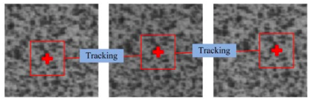
Figure 1: Spot tracking in images
|
 |
|
|
Image courtesy of CY Chang; L.C. Chen; W.C
Lee; and C.C. Ma. 2015, Measuring Full-Field Deformation and vibration
using Digital Image Correlation.
|
|
|
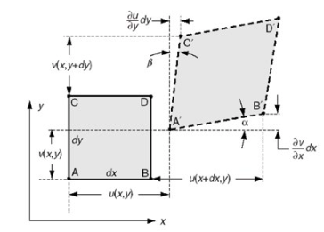
Figure 2: Graph of displacement and strain
after deformation
|
|
 |
|
|
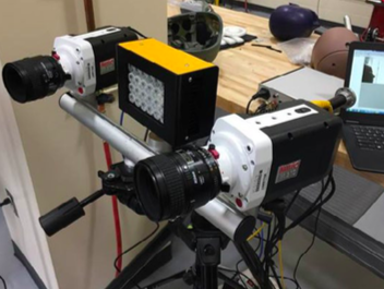
Figure 3: Full experiment set-up
|
|
 |
|
|
Image courtesy of CY Chang; L.C. Chen; W.C
Lee; and C.C. Ma. 2015, Measuring Full-Field Deformation and vibration
using Digital Image Correlation.
|
|
|
ADVANTAGE #2: MANY MEASUREMENT POINTS PROVIDE MORE
COMPLETE DATA DIC can be very beneficial for biological and medical studies because it can provide movement measurements that traditional techniques cannot. Researchers from Suzhou University in China are applying it to better understand the 3-D swimming movements of fish (Jiang, 2016). The researchers marked a speckle pattern onto fish and then used two Phantom high-speed cameras to collect images of the fish swimming. They collected 4,096 images and used a mathematical model of 3-D image correlation to rebuild the 3-D shape, strain, and swimming movement of the fish. Compared with methods used previously to study fish swimming, DIC provided improved data, including real-time tracking of any point on the body of the fish and surface displacement in more than one direction |
|
|
Image and video courtesy of S. Piland, PhD; T.
Gould, PhD; University of Southern Mississippi.
|
|
|
Figure 4: Camera set-up of Miro 310s for
experiment
|
|
 |
|
|
Figure 5: Video of impact at 3,333 fps
|
|
 |
|
|
Image and video courtesy of S. Piland, PhD; T.
Gould, PhD; University of Southern Mississippi.
|
|
|
Image and video courtesy of S. Piland, PhD; T.
Gould, PhD; University of Southern Mississippi.
|
|
|
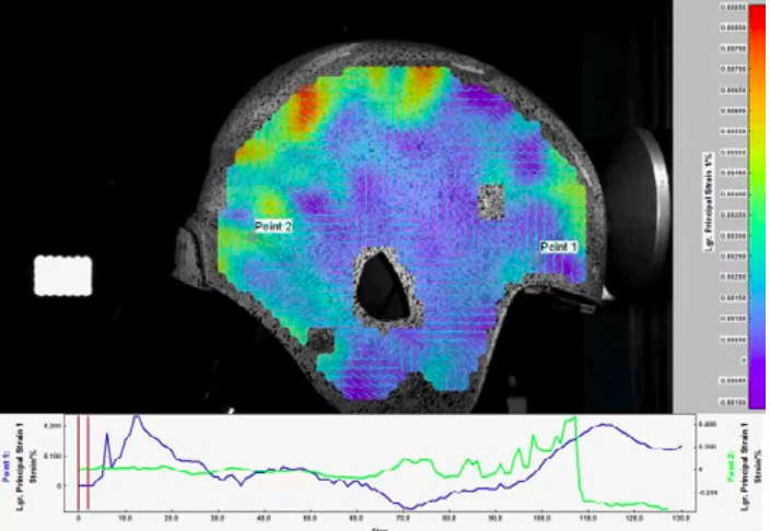
Figure 6: Video of principle strain from
impact
|
|
|
DIC ADVANTAGE #3: QUANTITATIVE DATA
Demonstrated Example: Conducting large-scale analysis and multidirectional movements. Conducting large-scale analysis with traditional sensors can be onerous due to the large space covered in the analysis. Also, multidirectional movement may not be possible without additional sensors or testing. DIC techniques offer a solution. Researchers from the University of Grenoble in France used DIC for full-field analysis to study how timber-framed structures respond to seismic activity (Sieffert, 2016). This analysis involved capturing full-field displacement of a full-scale timber-framed house undergoing simulated earthquakes on a shake table. The researchers had to balance the image resolution necessary to clearly see damage while gathering measurements at a full scale and to keep in mind the large number of pictures necessary to follow dynamic loading. The researchers used a high-speed Phantom v641 camera to track motion and Tracker software for analysis. For the most accurate DIC analysis, they used the camera's maximum resolution of 2560 x 1600 pixels, a resolution at which each pixel represents 2.16 millimeters on a wall of the house. At 150 frames-per-second (fps), an added 128 gigabytes of Phantom CineMag memory allowed a 40-gigabyte movie saved for each signal. For each simulated earthquake, the researchers acquired 7,599 images and tracked almost 4,000 pixels. The researchers also added contact measurement devices to the structure to measure shake table displacement. The DIC analysis provided displacements in both the x and y directions, which wasn't possible with the contact sensors. Also, the DIC technique exposed an opening in infill material and provided information on the flexural behavior of timber elements, which were otherwise not observable. The researchers concluded that DIC field displacement measurements provided direct proof of the seismic-resistant behavior of a filled timber-framed structure.
Basic DIC approaches can be combined with a variety of software packages to accomplish detailed analysis for a wide variety of specific applications. For example, researchers from Sandia National Laboratories used internally developed software and a cutting-edge DIC technique to monitor how well a mechanism is operating (Palaviccini, 2016). Because applying a traditional speckle pattern with paint might alter the shape or mass of the component under analysis, they used an advanced laser-marking technique to add points of reference on the component. Keeping the beam defocused and the laser settings below a calculated threshold prevented the laser from etching or ablating the material. The scientists modified DIC software to work with arbitrary shapes. This allows more of a component's surface to be tracked, which improves the accuracy of the analysis. The modified version was integrated into an automated vision system with a Phantom v1210 camera. This system could be used for monitoring components operating in a production unit in a manufacturing setting, for example.
The cameras used for DIC can make a big difference in the quality of data obtained and the types of analysis possible, and the type of analysis DIC supports can also determine the best camera for the job. The speckles typically used for DIC create fine high-contrast visual textures that are best imaged with high-resolution cameras that can maintain a high frame rate and good image quality. For many DIC applications, cameras with resolutions of 2 to 4 megapixels with frame rates of hundreds of frames per second (fps) work well. Measuring the stress or strain that results from a very fast phenomenon, such as an impact or a fast loading situation, requires a different type of camera. For example, a car manufacturer can use DIC to better understand how a metal door panel reacts to various types of impact that simulate real-world situations. These types of applications require cameras that can image fast enough to capture the quickly changing speckle pattern. Studying impact or fast loading situations can require a trade-off in camera resolution to achieve the high frame rates needed. Cameras that acquire tens of thousands of frames per second with 1 megapixel or less resolution work well for these applications. Some applications, such as vibration testing to discover how much a new dashboard material might vibrate under different road conditions, require extremely fast cameras. DIC can measure vibrations and a material's or part's response to vibrations in various locations over the entire analyzed field. These applications require a camera that can image at least twice as fast as the vibration frequency being measured. This means analysis of high vibration frequencies - where the response to vibration is in the high thousands or tens of thousands of hertz - requires a camera that can image at hundreds of thousands of frames per second depending on the application. Lighting can also influence the cameras used for DIC. If the material being analyzed is plastic or rubber, it might melt or change characteristics at increased temperatures. This means applying strong light to the sample could cause it to respond differently during analysis. A sensitive camera can lessen the amount of lighting necessary to obtain good images. It's important to also remember that the long recording times used for DIC can produce a large amount of data. Cameras with 10-gigabit download capability and fast integration with acquisition and analysis software can help ensure all the data is handled quickly.
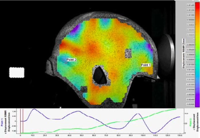
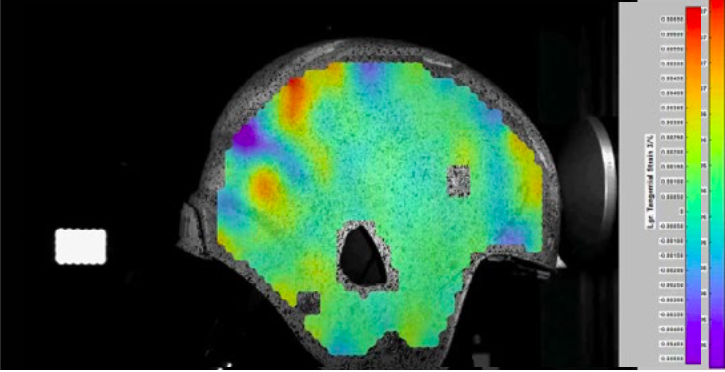
EXAMPLE OF DIC OUTPUT AND CAPABILITIES Researchers at the University of Southern Mississippi (USM) use 3-D-DIC to evaluate the performance of commercially available football helmets to blunt impacts common in American football. A helmet is placed on a linear impact table, where it is strapped to a simulation dummy head. The helmet is then struck by a pressurized punching device at high velocities to simulate blunt impact. The researchers used Phantom Miro 310s and Phantom v611s, with Dantec DIC software. Both the Phantom Miro 310 and the v611 are 1 megapixel cameras. Pictured earlier, figure 3 shows the complete DIC set-up and Figure 4 shows the camera set-up of the experiment. The helmet is covered with a random speckle pattern, and the impact is captured by the Phantom Miro 310s at 3,333 fps. Figure 5 shows the slow motion video of the impact. The Dantec software, using DIC algorithms, produced corresponding videos of the principle strain, displacement, and tangential strain caused by the impact. Figures 6, 7, and 8 show the corresponding videos. 3-D DIC provides this research effort with quantitative data of the entire helmet performance to blunt impacts, influencing the development of potentially safer helmets. In summary, DIC can provide full-field, quantitative information about stress, strain, and vibration that isn't available from other techniques. With the right cameras and software, this flexible technique can be used to measure extremely fast changes for a variety of applications and can greatly expand research results. |
 |
|
Image and video courtesy of S. Piland, PhD;
T. Gould, PhD; University of Southern Mississippi.
|
|
|
Figure 7: Video of displacement from impact
|
|
 |
|
|
Image and video courtesy of S. Piland, PhD;
T. Gould, PhD; University of Southern Mississippi.
|
|
|
Figure 8: Video of tangential strain from
impact
|
|
 |
|
|
Image and video courtesy of S. Piland, PhD;
T. Gould, PhD; University of Southern Mississippi.
|
|
|
|
|
If you like this page, please recommend and share it. |
||
| More | ||