|
||||||||||||||||||||||||||||||||||||||||||
|
||||||||||||||||||||||||||||||||||||||||||

Maximising digital image capture
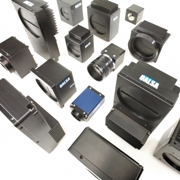
Area array and line scan cameras
What should you know before you choose and use digital imaging equipment?
Knowing how to obtain the most favourable outcome from
your machine vision application is often a challenging task and becoming
familiar with the types and functions of digital cameras and ancillary
equipment will help you make appropriate choices and so get it
right from the start.
|
What should you know about digital cameras and ancillary equipment? |
|
|
There are four key questions to ask before
deploying digital imaging equipment:
|
|
| 1 | What type of object image am I capturing? |
| 2 | What type of camera is best for my application? |
| 3 | How do I want to output from my camera? |
| 4 | What peripheral equipment do I need? |
About capturing objects
If the image you want to capture is of a stationary object or of an object
that moves in more than one dimension, then an area
array camera is what you need. Line
scan cameras, on the other hand, are deployed when the object
and the camera are moving relative to one another - where the object is
moving in only one dimension.
|
About cameras: |
||||
|
1
|
Area array cameras | |||
| Area
array cameras work by capturing images of stationary objects or
of objects that move in more than one dimension and the image is
provided to the camera as a series of lines composing a frame and
the camera generates a separate signal indicating the start and
end of the frame. Images from an area scan camera will not suffer
from blurring as long as the object’s motion during the exposure
period of the sensor array is not significant. |
||||
| Sensor types | ||||
| a | CCD
Sensors Many cameras incorporate features that allow for increased frame rates but sacrifice resolution. One feature available in CCD cameras that overcomes this limitation is binning, in which values of adjacent pixels are summed together into a single pixel. This allows reduced resolution images while increasing the apparent responsiveness of the camera. As an example, if a 1024x1024 resolution camera is binned two times vertically and two times horizontally, each 2x2 section of the sensor is reduced to a single pixel. The overall resolution of the image will then be 512x512, resulting in a four times reduction of the frame size, and a four times increase in responsivity, assuming the sensor doesn’t reach saturation Typically, one of three sensor architectures is used in a progressive scan camera with CCD sensor technology: |
|||
|
i
|
Interline
Transfer (ILT): the most common architecture. In interline
transfer technology, the accumulated charges on the sensor’s
capacitors are transferred on a line-by-line as is to a readout register.
Once the charges are read out, the remaining lines are shifted own.
Think in terms of a bucket brigade! While ILT is suitable for most low-end applications, it suffers from poor fill factors (approximately 30%). This is not adequate for most high-end applications, since details can literally fall between the cracks. To compensate for their poor fill factor, some ILT devices contain individual lenses on each pixel that focus most of the light onto the active part of the pixel region. |
|||
|
ii
|
Full frame arrays:
arrays of pixels that are exposed and then transferred directly from
the active region. The advantage of full frame technology is that it provides a 100% fill factor and is an effective use of the silicon. The disadvantage is that the light illuminating the sensor must be blocked during frame readout, either with a shutter (mechanical/LCD) or by strobing the light source to avoid image smear. If strobing or shuttering is not possible, the exposure time must be significantly longer than the frame readout time of the camera to minimize smear to an acceptable level. |
|||
|
iii
|
Frame transfer arrays consist of the active array
of pixels and a storage region. Once the image is exposed onto the
active array and following exposure, it is transferred to the storage
region, which is the same size as the active area but is covered
with a light shield to prevent further exposure of the acquired
image. |
|||
| b | CMOS: While CMOS sensors typically do not have the same low noise characteristics that CCD sensors do, their signal-to-noise ratio is improving, and CMOS has several significant benefits over CCD sensors which include: high speed, resistance to blooming, and low power consumption. Unlike CCD sensors, CMOS sensors can be addressed randomly, which easily allows an ROI (region of interest) readout of the image. CMOS cameras can increase frame rates by allowing the user to select a region of interest within the overall image and sending only that region out. As an example, a CMOS camera may have a total sensor resolution of 1024x1024 pixels. The CMOS camera has the capability of selecting the pixel addresses to be sent out. If the entire array is required, then the addresses selected will be 0,0 and 1023,1023. The user may decide to select a portion of the image, such as 300,200 and 700,600, to be sent from the camera. The camera will then send only the selected lower resolution portion of the overall image, at a much faster frame rate. Overall, CMOS sensor technology has several advantages over CCD technology, but, to date, the factor limiting wide acceptance has been lower image quality due to higher noise levels, due to amplifiers required at each pixel location, and hot pixels. Additionally, because of the extra circuitry at each location, the fill factor is lower than for many CCD technologies (full frame CCD provides a 100% fill factor) |
|||
| 2 | Line scan cameras | |||
|
Line scan cameras are the technology of choice when the object
and camera are moving relative to one another. Line scan and high
sensitivity line scan cameras are well suited to applications where
the objects being imaged are in motion and are moving in only one
dimension. Common applications for line scan cameras include:
web inspection, flat panel display inspection,
bottle inspection, and postal/parcel sorting. High-sensitivity line scan cameras
are not a good option when web speed varies unpredictably
because it is not possible to control exposure with these cameras.
In some applications where high sensitivity is required, binning
can be used at the cost of lowered resolution. Not all cameras come
with binning as a standard feature, which
should be kept in mind when choosing a line scan
camera. |
||||
|
About output: Digital Data Formats and Interfaces |
|
|
Which digital data format and camera interface
is right for your application?
|
|
| CameraLink | CameraLink
is the latest evolution in LVDS cameras and standardizes the interface
between digital cameras and frame grabbers simplifying the connection
to standard, off-the-shelf cables. CameraLink uses a serial transfer
technology and thus requires significantly fewer conductors than previous
parallel signal transmissions. This simplification results in smaller,
more flexible cables, and lowered cost. CameraLink can also support multiple output cameras and enable high-speed imaging systems. |
| FireWire and USB | Firewire and USB are relatively recent innovations in camera output formats. Each of these fairly simple interfaces is accomplished using standard cables and existing computer ports. Currently, their data transfer speeds are limited, and, therefore, these interfaces are restricted to relatively slow, single-channel cameras. |
| GigE Vision | GigE Vision is the
first machine vision digital interface designed to use networking
technologies. These days, networking is ubiquitous in that most PCs
have 1, if not 2, Gigabit interfaces. This is not the case with Firewire
which is typically only available in high-end multimedia computers.
There has been a tremendous investment in networking technologies over the last decades outside of the machine vision market. GigE Vision directly leverages from them by using their electrical components and specifying a protocol adapted to camera control and real-time transmission of images and video. The main benefit of using Ethernet to machine vision is the opportunity to use long cables (up to 100 meters for copper) with a digital camera. This is the first time analog cameras using long shielded cables can be replaced using a standard digital interface (all other technologies such as Firewire, USB and CameraLink cannot accommodate more than 10 meters over copper). And because the images are transferred as Ethernet packets, they are protected by a checksum. This latter property ensures that if a transmission error occurs, the application can ask for retransmission of the corrupted information. The available bandwidth of Gigabit Ethernet (slightly higher than 100 MB/s) is also well suited to a majority of image processing applications. GigE Vision provides the assurance of interoperability among products coming from different vendors. |
|
About peripherals: |
|
|
What ancillary equipment do you need?
Once a camera has been chosen for an application, the remaining equipment can be selected. Your choice of this equipment will be dependent on the camera and the application. |
|
| Optics and lighting | Optics
and lighting should be selected to comply with the requirements of
the selected camera such as the lens mount and the spectral response.
Lighting and optics is a wide-ranging topic that is beyond the scope
of what can be covered in this article. However, selecting the right lighting and optics for each application is absolutely critical, and often may have more of an impact on the success of the machine vision system than selecting the proper camera. No camera, no matter how well designed or selected, will perform to its maximum capabilities if either the lighting or optics are poorly matched. |
| Software | Software
is application-driven and may be dependent on the type of
interface to the acquisition system. In relation to camera selection, software should be selected to provide the best control for the required features of the camera. For example, many cameras provide for exposure control via an external signal such as EXSYNC. While this is ultimately a hardware control signal, many applications require the ability to change the exposure under software control. If this interface is crude or nonexistent, the user will be mired in developing this interface from scratch. The frame grabber software should provide an easy-to-use interface to these and other camera control parameters. Beyond this, software selection becomes highly dependent on the application. The choice of a software vendor should include such selection criteria as camera/frame grabber interface, image-processing algorithms offered, data transfer and handling sophistication, robustness of the package, and ease of integration. Nearly all applications need some method of triggering for an acquisition to take place and, therefore, the manner in which this can be accomplished is dependent on the acquisition system interface. In many applications, the system must be synchronized with an external event, such as a part-in-place sensor, to initiate acquisition. The ability of the camera and frame grabber to respond reliably to an external trigger is usually a key requirement. Additionally, notification of a failure to deliver the requested image is often just as critical. Using a frame grabber and camera that can provide this notification and event monitoring can greatly increase the resulting system reliability. The demand for improved reliability has resulted in the development of various innovations in the industry to control, monitor and correct the image acquisition process from the time that an external trigger event occurs to the moment the data is sent to the host, providing traceability when errors do occur and permitting recovery from those errors. Line scan cameras often operate in concert with a shaft encoder and therefore require a frame grabber that can properly interface to common shaft encoder signals. The ability to fire a strobe and properly align this signal with the trigger signal can also be important. |
| Cabling | CameraLink standardizes
the cabling required to interface to a digital camera. In addition
to the convenience and economy of being able to obtain cables from
several sources, CameraLink cables also have many fewer conductors
than required for older parallel signal standards. Whether using CameraLink, LVDS, RS-422, or TTL digital cameras, the cables selected should be of high quality and adhere to the specifications for the standard. For example, using a cable that exceeds the recommended length can result in data loss or noise sensitivity, or may have unexpected consequences such as variable results from camera to camera or frame grabber to frame grabber. One advantage of Gigabit Ethernet technology is its ability to transmit data over standard CAT-5e and CAT-6 cables to distances of up to 100m allowing for a greater distance between the camera and inspection system. |
| Bayer mosaic filters | Recently, Bayer
mosaic filters have been integrated into sensors to provide colour
output. Bayer color cameras are typically available at a much lower cost than a three-chip RGB sensor. While this article will not cover the advantages and drawbacks of Bayer arrays, it is worth noting that, if a Bayer output camera is selected, a conversion will be required in order to view the colour image. If a Bayer pattern camera is used, be sure that the frame grabber or software can perform the required conversions at the required rates. |
|
WHAT STEPS SHOULD I TAKE WHEN SELECTING A CAMERA? |
||||
| 1 | Define the minimum object feature size |
6
|
Determine the necessary bit depth | |
| 2 | Determine the minimum camera sensor resolution |
7
|
Consider what additional camera features may be necessary | |
| 3 | Select the appropriate available camera resolution |
8
|
Determine the interface required for the acquisition system | |
| 4 | Consider object movement and determine the appropriate camera sensor structure |
9
|
Select acquisition device and interface to camera | |
| 5 | Determine the necessary camera spectral response |
10
|
Select the additional ancillary equipment dependant on the camera features and type of interface | |
|
NOTE: other
factors may precede camera selection for some imaging applications;
for example, a camera must be selected to fit into an existing mounting
system, or to connect to an existing interface
|
||||
|
GLOSSARY |
|
| A frame composed of two intertwined fields of alternating even and off lines [back] | |
| CCD | Charged Coupled Device. A sensor consisting of an array of photosensitive areas and adjoining capacitors for storing the accumulated charge [back] |
| CMOS | Complementary Metal Oxide Semiconductor [back] |
| Blooming | The charge accumulated on a pixel can leak to adjacent areas if the charge is too great, which may occur if a CCD sensor is saturated [back] |
| Hot pixels | Hot pixels are single pixels that suffer from significant leakage current compared to neighboring pixels, such that in dark these pixels are elevated compared to neighbouring pixels [back] |
| TDI |
Time, Delay and Integration [back] |
| Binning | When binning, a camera combines the charge collected by two or more pixels. [back] |
| TTL | Transitstor-transistor logic [back] |
| LVDS | Low voltage differential signal [back] |
Adept Electronic Solutions are "The Machine Vision and Imaging Specialists" and distributor of cameras and auxiliary equipment products in Australia and New Zealand. To find out more about any machine vision product please email us at: adept@adept.net.au or call us at Perth (08) 92425411 / Sydney (02) 99792599 / Melbourne (03) 95555621 or use our online contact us page.
|
If you like this page, please recommend and share it. |
||
| More | ||